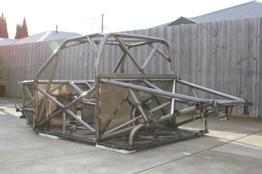
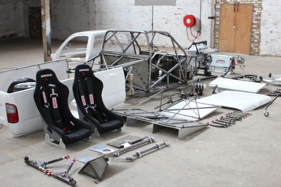
It’s now been ten years since the tube chassis Hilux has been completed and when I think back on that build I reflect on the fast paced learning curve that I went through, in the ten years that have passed I have added a lot of new tools to my intellectual toolkit that have made things a lot more precise and refined.
Let me say this though, NOTHING replaces the need to just get in and do things, right or wrong the actions you take will quickly stack up and the knowledge gained from this will pave your way forward. Understanding how to do something is difficult when you havn’t done it before so im excited to use the knowlege I have gained from previous projects and put it to use in this one.
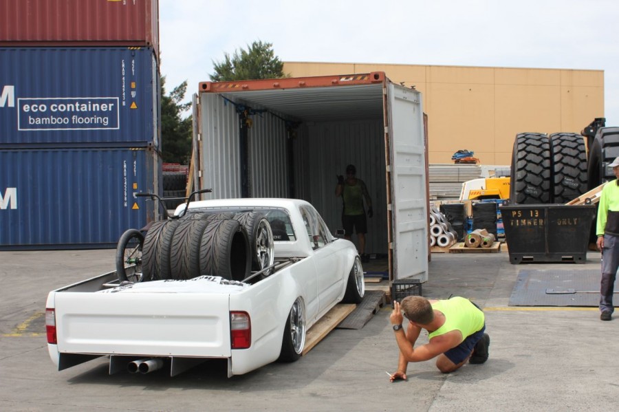
You might remember the S15 roll cage post HERE that begun with the scanning of the interior depicted HERE and this was my first opportunity to use 3D scanning technology thats implemented in high end motorsport applications. You cirtainly dont need a 3D scanner to design a roll cage but if you were going through the process of designing one for FIA Homoligation and simulation then you would have difficulty doing it without one.
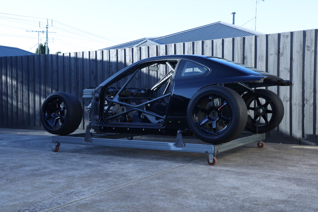
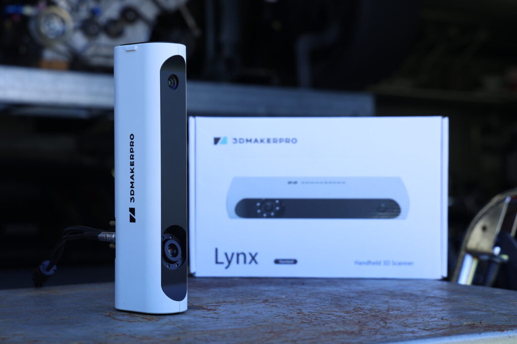
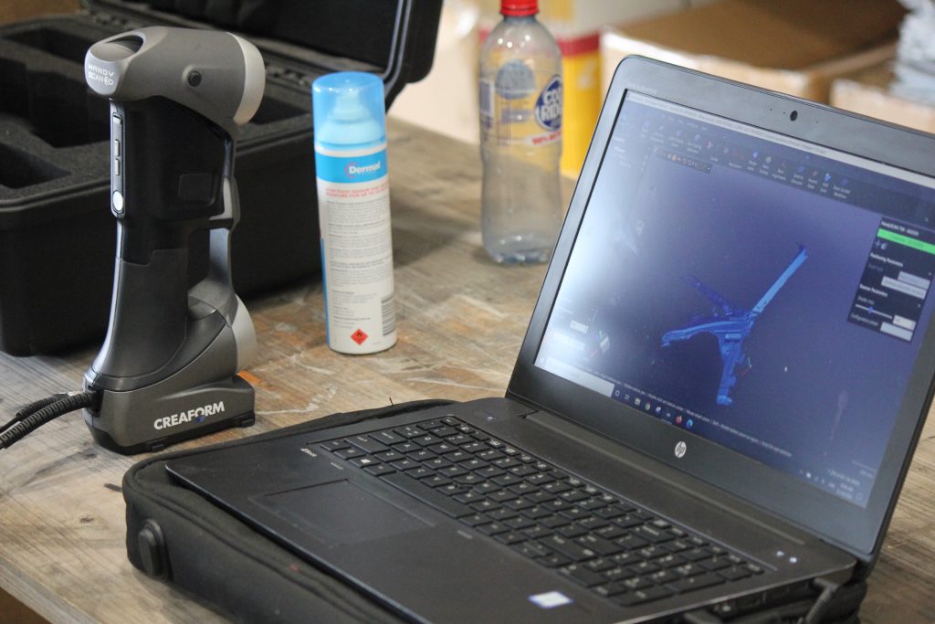
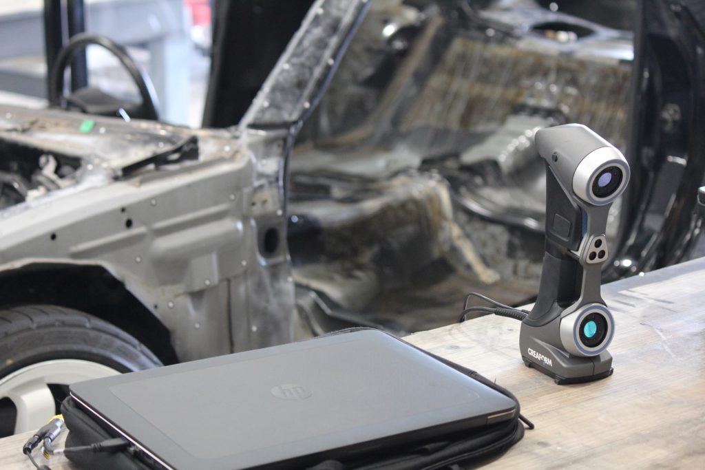
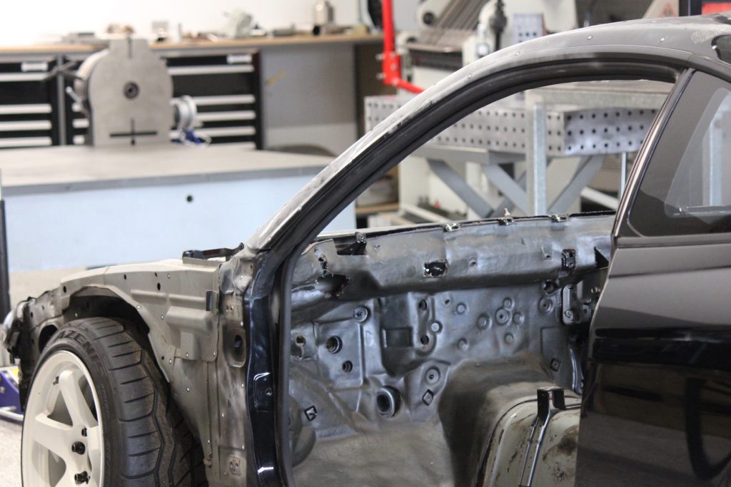
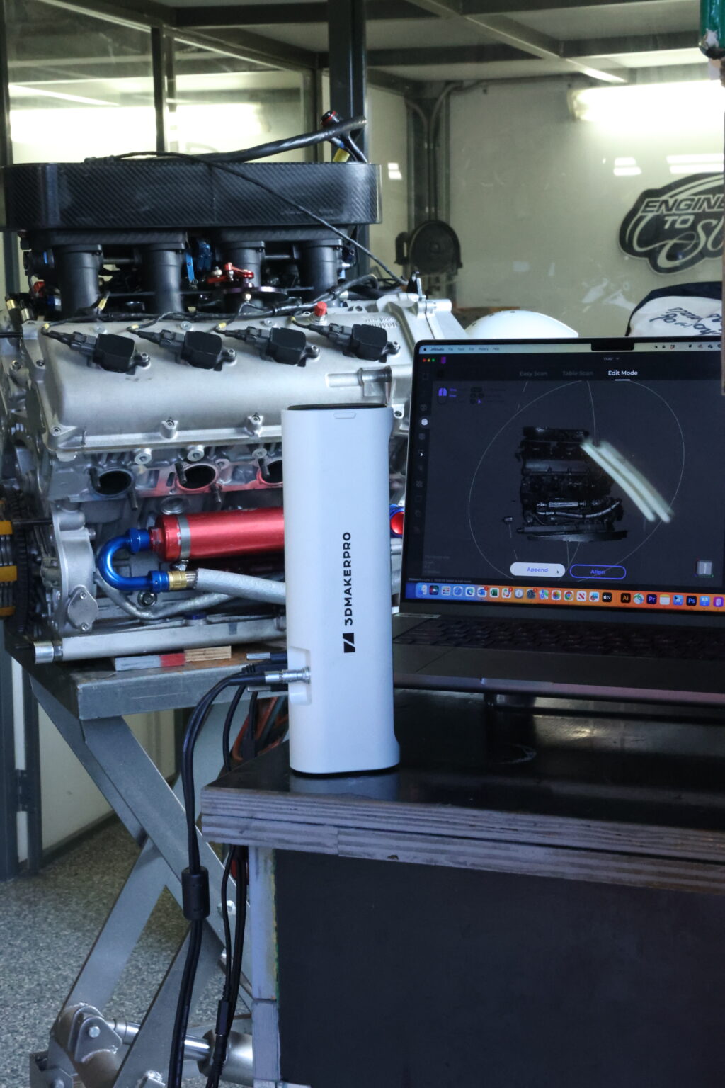
Fastforward to now, the S15 has been cut up to accept a lot more freedom in design and this is where the 3D scanner makes a return. The Creaform scanner I borrowed to initially scan the S15 was worth close to $75k and in a few short years the market has been flooded with affordable options such as the 3DMakerPro that I am using.
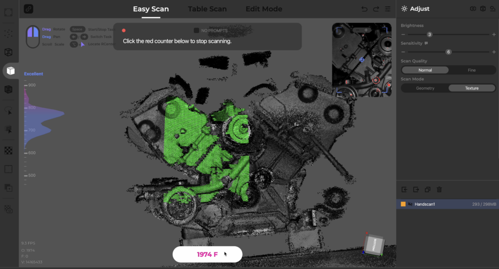
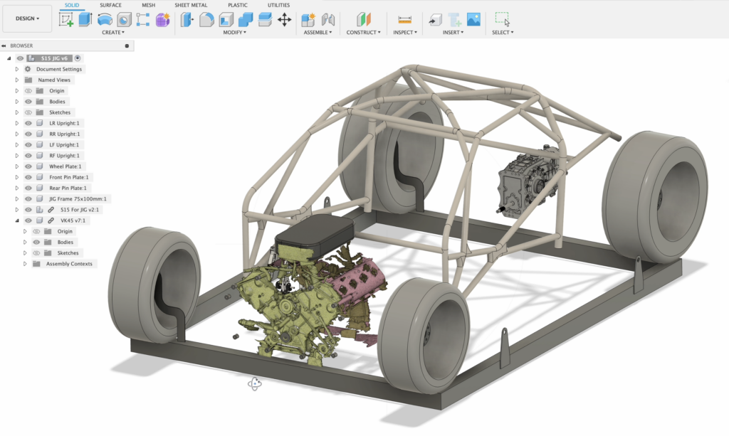
The greatest thing about the 3DMakerPro is the open source JMStudio software that allows the scans to be aligned and cleaned up ready for CAD development. This allowed me to complete scans on the VK45 motor and bring these into CAD to start developing the model for the front and rear motot mounts that will have very important roles in the front end structure of the S15.

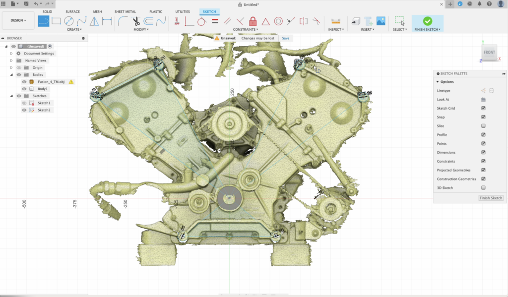
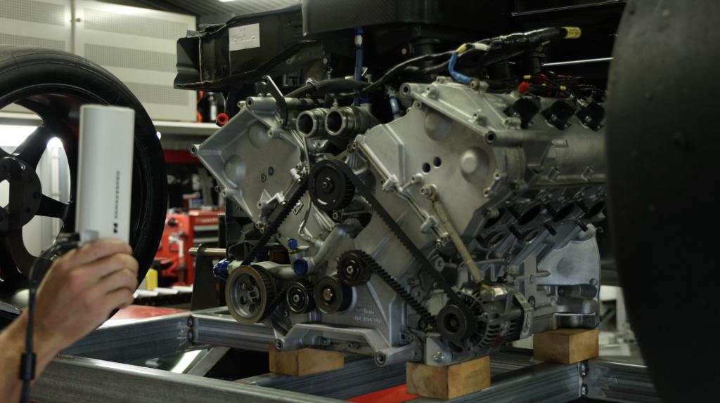
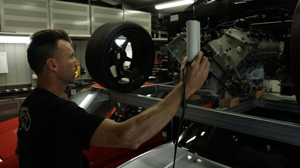
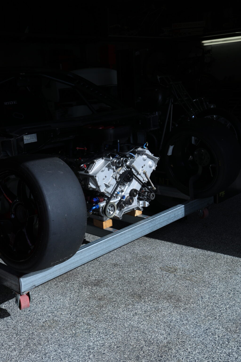
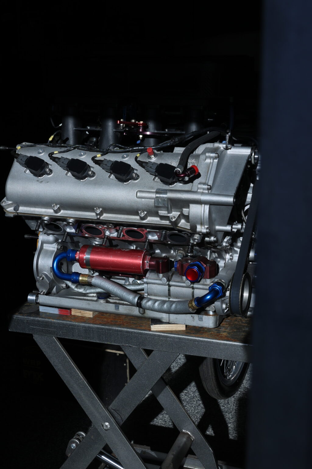
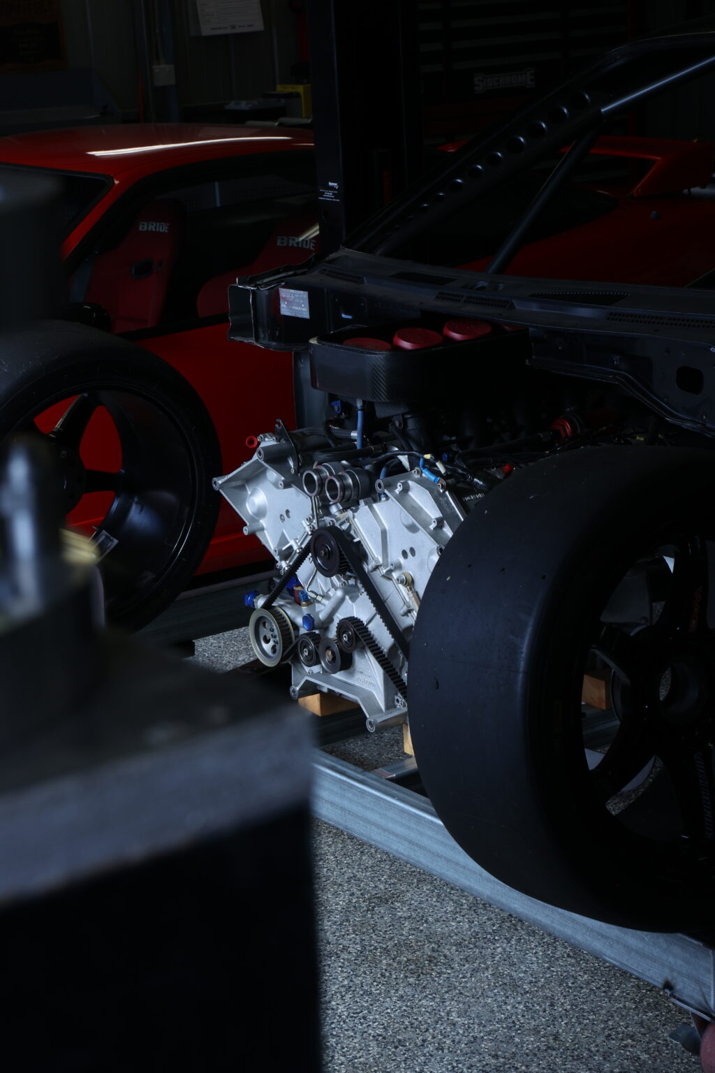
To begin I scanned the VK45 motor and focused on the front mounting provisions that would have secured the entire driveline to the Indy cars rear bulkhead and from here I can develop a motor plate that houses the 6 mounting bolts for the motor, steering rack mounts, forward upper and lower suspension wishbone mounting provisons and damper mounts that utilse rocker pivots.
On the rear I needed to scan the same mounting structure to facilitate a rear motor plate that creates a bulkead mounting provision that will create the firewall of the chassis, mount the starter motor, the dry sump oil tank and then a structural support that reinforces the suspension rockers on the front of the motor.
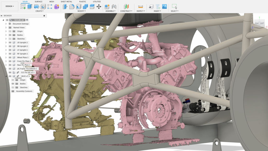
Yes a ruler could have been used to pick these points but the amount of extra information a scan provides is super powerful, I could have spent 2 hours in the garage measuring everything, creating templates and possibly introducing costly errors in the process. Instead a morning spent scanning the necassary areas gives me every detail I will need to know without ever revisiting the garage with a tapemeasure.
If you’re working with an external engineer, a part supplier, a machinist or building a car externally then 3D scanning can be a huge time saver that allows you to get more information than you will ever need. Introduce these scans into your CAD model, ask suppliers for a STEP file of the parts your looking to add in and see how it all fits before even getting your hands dirty.
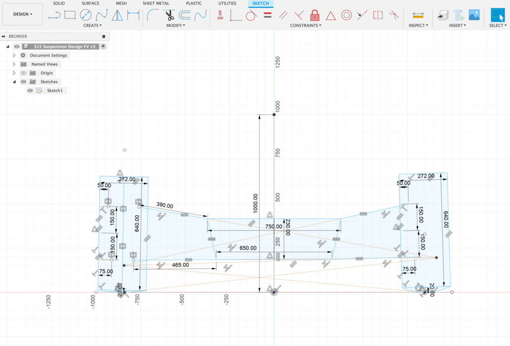
I’m now using these scans to develop the suspension package, a double A arm wishbone setup is in its early stages of development, I have shared with you my drawings in Fusion 360 to help you develop your own if you are interested. Check out the post in the S15 Project page HERE and stay tuned for more information on this as I develop out my ideal race car.
Thanks for reading.